Engineering & Industrial · August 27, 2026
Cylindrical Pressure Vessel Volume and Wall Thickness Allowance
Calculate pressure vessel internal volume, shell wall thickness, and corrosion allowances using ASME Boiler and Pressure Vessel Code Section VIII UG-27.

- Cylindrical Pressure Vessel Volume and Wall Thickness Allowance
- The Formula: ASME Section VIII Division 1 (UG-27) Derivation
- Circumferential Hoop Stress (Governing Equation)
- Longitudinal Stress Check
- Internal Shell and Head Volume
- Reference Data: ASME Material Allowable Stress Values and Joint Efficiencies
- ASME Joint Efficiency Values (E)
- Worked Examples
- Worked Example 1: Metric Compressed Air Receiver Tank
- Worked Example 2: Imperial Stationary LPG Storage Pressure Vessel
- Worked Example 3: Edge Case Vacuum Distillation Column Under Full External Vacuum
- Common Mistakes in Pressure Vessel Sizing and Fabrication
- Related Pressure Vessel and Tank Engineering Resources
Cylindrical Pressure Vessel Volume and Wall Thickness Allowance
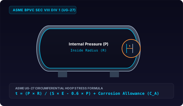
Cylindrical pressure vessel shell thickness uses t = (P × R) / (S × E - 0.6P) + CA. For a 48-inch vessel at 250 PSI with SA-516 Grade 70 steel (S = 20,000 PSI, E = 1.0), required thickness is 0.428 inches.
Industrial pressure vessels contain liquids and gases at pressures significantly higher than atmospheric. From refinery distillation towers to chemical reactors and compressed air receivers, mechanical engineers design cylindrical shells to strict standards established by the American Society of Mechanical Engineers (ASME Boiler and Pressure Vessel Code Section VIII Division 1).
The Formula: ASME Section VIII Division 1 (UG-27) Derivation
A pressurized cylindrical shell experiences two primary normal stress components: circumferential (hoop) stress σ_θ acting around the perimeter, and longitudinal (axial) stress σ_L acting parallel to the length axis.
Circumferential Hoop Stress (Governing Equation)
Under ASME Section VIII Division 1 paragraph UG-27(c)(1), the minimum required thickness of a thin cylindrical shell under internal pressure where thickness does not exceed one-half the inside radius (t ≤ 0.5R) or pressure does not exceed 0.385SE:
t_shell = (P × R / S × E - 0.6 × P) + C_AWhere:
t_shellis the minimum required thickness of the shell (inches or millimeters).Pis the internal design pressure (PSIorMPa).Ris the inside radius of the shell course before corrosion allowance is added (inchesormm).Sis the maximum allowable stress value of the material from ASME Section II Part D (PSIorMPa).Eis the weld joint efficiency factor (1.00for full RT,0.85for spot RT,0.70for no RT).C_Ais the specified corrosion allowance (inchesormm).
Longitudinal Stress Check
For longitudinal joints under UG-27(c)(2):
t_longitudinal = (P × R / 2 × S × E + 0.4 × P) + C_ABecause the circumferential stress equation produces roughly double the required thickness of the longitudinal equation, circumferential stress dictates shell plate selection.
Internal Shell and Head Volume
The internal volume consists of the cylindrical shell plus the two formed end heads:
V_shell = π × R^2 × L_straightFormed head volumes for standard geometries:
- Hemispherical Head (Single):
V_hemi = (2 / 3) π R^3 = (π D^3 / 12)- Standard ASME 2:1 Semi-Elliptical Head (Single):
V_2:1 elliptical = (π D^3 / 24) ≈ 0.1309 × D^3- ASME Flanged and Dished (Torispherical) Head:
V_torispherical ≈ 0.0847 × D^3To compute hollow wall material weight and volume, explore our hollow cylinder calculator and our cylinder volume from diameter tool.
Reference Data: ASME Material Allowable Stress Values and Joint Efficiencies
The following engineering reference table summarizes maximum allowable tensile stress values (S) for common pressure vessel carbon steels and stainless steels under ASME Section II Part D, alongside standard joint efficiencies.
| Material Specification | Nominal Composition | Tensile Strength (PSI / MPa) | Yield Strength (PSI / MPa) | Max Allowable Stress at 100°F (PSI / MPa) | Max Allowable Stress at 300°F (PSI / MPa) | Max Allowable Stress at 500°F (PSI / MPa) |
|---|---|---|---|---|---|---|
| SA-516 Gr 70 | Carbon Steel Plate | 70,000 PSI (485 MPa) | 38,000 PSI (260 MPa) | 20,000 PSI (138 MPa) | 20,000 PSI (138 MPa) | 19,400 PSI (134 MPa) |
| SA-516 Gr 60 | Carbon Steel Plate | 60,000 PSI (415 MPa) | 32,000 PSI (220 MPa) | 17,100 PSI (118 MPa) | 17,100 PSI (118 MPa) | 16,600 PSI (114 MPa) |
| SA-106 Gr B | Extruded CS Pipe | 60,000 PSI (415 MPa) | 35,000 PSI (240 MPa) | 17,100 PSI (118 MPa) | 17,100 PSI (118 MPa) | 16,600 PSI (114 MPa) |
| SA-240 304L | Austenitic Stainless | 70,000 PSI (485 MPa) | 25,000 PSI (170 MPa) | 16,700 PSI (115 MPa) | 13,800 PSI (95 MPa) | 11,800 PSI (81 MPa) |
| SA-240 316L | Moly Stainless Plate | 70,000 PSI (485 MPa) | 25,000 PSI (170 MPa) | 16,700 PSI (115 MPa) | 14,100 PSI (97 MPa) | 12,300 PSI (85 MPa) |
ASME Joint Efficiency Values (E)
| Weld Joint Description | Radiography NDE Level | Joint Efficiency Factor (E) |
|---|---|---|
| Type 1 Butt Joint | Full 100% Radiography (RT-1 / RT-2) | E = 1.00 |
| Type 1 Butt Joint | Spot Radiography (RT-3) | E = 0.85 |
| Type 1 Butt Joint | Visual Examination Only (RT-4) | E = 0.70 |
| Type 2 Single Welded Butt with Backing Strip | Spot Radiography | E = 0.80 |
Worked Examples
Worked Example 1: Metric Compressed Air Receiver Tank
An industrial plant requires a compressed air receiver vessel with an inside diameter of 1,000 mm (R = 500 mm) and a straight shell length of 2,500 mm. Operating conditions: design pressure P = 1.60 MPa (16.0 bar), design temperature 50^\circC, material SA-516 Grade 70 (S = 138.0 MPa), spot radiography (E = 0.85), and a specified corrosion allowance C_A = 2.0 mm. Calculate the minimum required shell thickness and internal shell volume in liters.
Step 1: Calculate denominator term (S × E - 0.6 × P).
Denominator = (138.0 × 0.85) - (0.6 × 1.60) = 117.30 - 0.96 = 116.34 MPaStep 2: Calculate pressure-radius numerator (P × R).
Numerator = 1.60 MPa × 500.0 mm = 800.00 MPa · mmStep 3: Calculate required pressure shell thickness (t).
t_pressure = (800.00 / 116.34) = 6.8764 mmStep 4: Add corrosion allowance (C_A = 2.0 mm).
t_total = 6.8764 mm + 2.0000 mm = 8.8764 mmThe fabricator specifies standard 10.0 mm carbon steel plate.
Step 5: Calculate internal cylindrical shell volume.
V_shell = (π × D^2 / 4) × L = (3.14159265 × 1.00^2 / 4) × 2.50 = 0.785398 × 2.50 = 1.963495 m^3 = 1963.50 litersYou can check internal liquid capacities with our cylinder volume in liters tool.
Worked Example 2: Imperial Stationary LPG Storage Pressure Vessel
A chemical plant fabricates an ASME Section VIII Division 1 horizontal propane storage bullet. Inside radius R = 24.0 inches (48.0 in inside diameter), straight shell length L = 120.0 inches (10.0 ft). Design parameters: P = 250.0 PSI, design temperature 100^\circF, material SA-516 Grade 70 (S = 20,000 PSI), 100% full radiography (E = 1.00), and corrosion allowance C_A = 0.125 inches (1/8 in). Calculate the minimum required shell thickness, specified plate size, and internal shell capacity in gallons.
Step 1: Calculate denominator term.
Denominator = (20000 × 1.00) - (0.6 × 250.0) = 20000 - 150 = 19850 PSIStep 2: Calculate numerator term.
Numerator = 250.0 PSI × 24.0 in = 6000.0 PSI · inStep 3: Calculate pressure thickness and add corrosion allowance.
t_pressure = (6000.0 / 19850) = 0.302267 inchest_total = 0.302267 + 0.125000 = 0.427267 inchesThe engineer specifies standard 0.500-inch (1/2-inch) nominal steel plate.
Step 4: Calculate internal shell volume in gallons.
V_shell, cu ft = (π × (2.0 ft)^2 × 10.0 ft / 1) = 3.14159265 × 4.0 × 10.0 = 125.6637 cu ftV_shell, gal = 125.6637 × 7.480519 gal/cu ft = 940.03 gallonsYou can verify these measurements with our cylinder volume in gallons tool and tank volume calculator.
Worked Example 3: Edge Case Vacuum Distillation Column Under Full External Vacuum
A petrochemical vacuum distillation column with inside diameter D = 72.0 inches (R = 36.0 in) and straight length of 240.0 inches operates under full internal vacuum (equivalent to an external differential pressure of P_ext = 15.0 PSI). Under ASME Section VIII Division 1 UG-28, cylindrical shells under external pressure fail by elastic hoop buckling rather than material yield. To prevent buckling without excessively heavy plate, the designer installs external stiffening rings spaced every 48.0 inches along the shell. Calculate shell thickness required for external stability.
Step 1: Determine geometric ratios.
\frac(L_unsupported)(D_outer) = (48.0 in / 72.75 in) = 0.6598Assumed trial thickness t = 0.375 inches (3/8 in)\frac(D_outer)(t) = (72.75 / 0.375) = 194.0Step 2: Check allowable external working pressure (P_a).
From ASME Section II Part D Subpart 3 Chart CS-2 for carbon steel at 300°F:
Strain Factor A = (0.125 / (D_o / t) × (L / D_o)) = (0.125 / 194.0 × 0.6598) = 0.000976Stress Factor B = 10,500 PSIP_a = (4 × B / 3 × (D_o / t)) = (4 × 10500 / 3 × 194.0) = (42000 / 582.0) = 72.16 PSIBecause allowable external pressure P_a = 72.16 PSI comfortably exceeds the design 15.0 PSI vacuum load, the 0.375-inch plate with 48-inch ring spacing is verified as safe against buckling. For more on calculating structural steel weights, see our steel coil volume and weight calculation guide.
Common Mistakes in Pressure Vessel Sizing and Fabrication
-
Omitting Mill Undertolerance on Raw Steel Plate ASTM A20 plate specifications permit a mill manufacturing thickness undertolerance of 0.010 inches (0.25 mm). If a calculation yields a required minimum thickness of 0.500 inches and 0.500-inch nominal plate is ordered, the as-delivered plate may measure 0.490 inches, causing immediate Authorized Inspector rejection. Designers must specify plate nominal thickness that exceeds calculated minimums by the mill undertolerance.
-
Neglecting Head Thinning During Cold Dishing and Spinning Forming flat steel discs into 2:1 semi-elliptical or torispherical heads stretches the metal, reducing knuckle thickness by 10% to 15%. Fabricators must start with blank plate that is 1/16 to 1/8 inch thicker than the calculated minimum head thickness to maintain compliance after pressing.
-
Confusing Maximum Allowable Working Pressure (MAWP) with Design Pressure Design pressure is the specified internal pressure used to calculate minimum required plate thickness. Once standard plate thickness is selected (which is thicker than calculated minimum), the Maximum Allowable Working Pressure (MAWP) is recalculated using the actual plate thickness minus corrosion allowance. The hydrostatic test pressure under UG-99 is set to
1.3 × MAWP. -
Ignoring Hydrostatic Head Weight on Tall Vertical Column Bases In tall vertical distillation columns or storage vessels exceeding 40 feet in height, the static liquid head exerts significant additional internal pressure on the bottom shell course. For a 50-foot water column, static pressure adds
50 × 0.4335 = 21.68 PSIto the design pressure at the base. Bottom shell courses must be sized for combined operating pressure plus static liquid head. -
Using Room Temperature Allowable Stress for High-Temperature Service Allowable stress (
S) drops drastically as metal temperatures rise above 400°F due to material softening and creep deformation. Using SA-516 Grade 70 allowable stress at 100°F (20,000 PSI) for a boiler operating at 650°F (where allowable stress drops to 18,800 PSI) underestimates required wall thickness by 6.4%, violating ASME safety margins.
Related Pressure Vessel and Tank Engineering Resources
For related engineering formulas, tank charts, and cylinder calculators, review our technical resources:
- How engineers calculate fuel tank capacity
- Horizontal tank dip stick chart calculation
- Propane tank fill percentage and the 80 percent safe fill rule
- Hydraulic accumulator sizing and gas precharge volume
- HVAC round duct volume and air changes per hour
- Transformer cylindrical tank oil capacity
- Hollow cylinder volume calculator
- Cylinder weight calculator
Applying ASME Section VIII Division 1 formulas ensures structural safety, mechanical integrity, and regulatory compliance across high-pressure industrial systems.