Engineering & Industrial · August 27, 2026
HVAC Round Duct Volume and Air Changes per Hour Calculation
Calculate HVAC round duct volume, airflow velocity, and room air changes per hour (ACH). Includes SMACNA standards, formulas, tables, and worked examples.
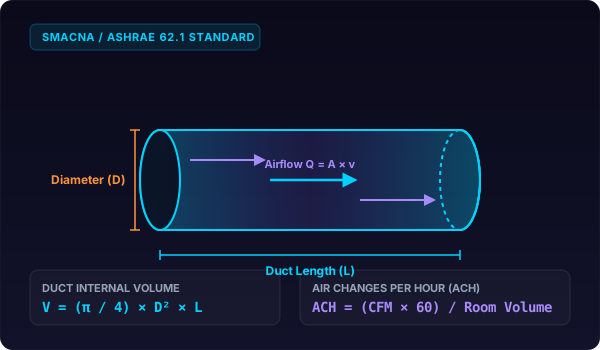

- HVAC Round Duct Volume and Air Changes per Hour
- The Formula: Round Duct Geometry and Airflow Dynamics
- Cross-Sectional Area
- Internal Duct Volume
- Volumetric Airflow and Air Velocity
- Duct Air Residence Time
- Room Air Changes per Hour (ACH)
- Reference Data: Standard Round Duct Dimensions and Air Capacities
- Worked Examples
- Worked Example 1: Metric Commercial Branch Duct
- Worked Example 2: Imperial Residential Trunk Line and Room Ventilation
- Worked Example 3: Edge Case High-Velocity Industrial Exhaust System
- Common Mistakes in Duct Volume and Airflow Calculations
- Practical Engineering Considerations for Duct Sizing
HVAC Round Duct Volume and Air Changes per Hour
Round duct volume uses V = π × r² × L. For a 12-inch duct (r = 0.5 ft) spanning 20 feet, volume is 15.71 ft³. At 800 CFM, air replaces every 1.18 seconds across the run.
Heating, ventilation, and air conditioning (HVAC) systems rely on precise duct geometry to balance thermal comfort, indoor air quality, and acoustic performance. Whether balancing a commercial variable air volume (VAV) system or verifying ventilation compliance under ASHRAE Standard 62.1, calculating duct internal volume and room exchange rates is fundamental.
The Formula: Round Duct Geometry and Airflow Dynamics
A circular duct is a geometric cylinder. The mathematical derivation begins with the cross-sectional area of the circle multiplied by the linear length of the duct run.
Cross-Sectional Area
For a duct with inside diameter D or radius r:
A = π × r^2 = (π × D^2 / 4)When working in US Customary units where diameter is measured in inches and area is required in square feet:
A_sq ft = \frac(π × D_in^2)(4 × 144) = \frac(π × D_in^2)576 ≈ 0.005454 × D_in^2Internal Duct Volume
Multiplying cross-sectional area by duct length L yields internal volume:
V_duct = A × L = (π × D^2 × L / 4)For fast conversions from measured dimensions, you can verify calculations with our cylinder volume from diameter calculator or compute fluid capacity using our cylinder volume in cubic feet tool.
Volumetric Airflow and Air Velocity
The volumetric flow rate Q passing through a round duct equals the cross-sectional area multiplied by the mean air velocity v:
Q = A × v- In US Customary units:
Qis measured in cubic feet per minute (CFM),Ain square feet (ft^2), andvin feet per minute (FPM). - In SI Metric units:
Qis measured in cubic meters per second (m^3/s) or liters per second (L/s),Ain square meters (m^2), andvin meters per second (m/s).
Duct Air Residence Time
The time t that an air packet spends traveling through a duct section equals internal volume divided by volumetric flow rate:
t_seconds = \frac(V_duct)(Q) × 60Room Air Changes per Hour (ACH)
Air Changes per Hour (ACH) measures how many times the total air volume of a room or building space is completely replaced by mechanical ventilation within one hour.
ACH = \frac(Q_CFM × 60)(V_room, cu ft)In metric units:
ACH = \frac(Q_m^3/h)(V_room, m^3) = \frac(Q_L/s × 3.6)(V_room, m^3)Reference Data: Standard Round Duct Dimensions and Air Capacities
The following table summarizes standard spiral sheet metal round duct sizes under SMACNA HVAC Duct Construction Standards, showing cross-sectional area, internal volume per 10 feet of duct run, and airflow capacity at typical commercial velocity (1,200 FPM).
| Nominal Diameter (in) | Inside Diameter (mm) | Cross-Section Area (sq ft) | Volume per 10 ft Run (cu ft) | Airflow at 1,000 FPM (CFM) | Airflow at 1,200 FPM (CFM) | Airflow at 1,500 FPM (CFM) |
|---|---|---|---|---|---|---|
| 4 in | 101.6 mm | 0.0873 sq ft | 0.873 cu ft | 87.3 CFM | 104.7 CFM | 130.9 CFM |
| 6 in | 152.4 mm | 0.1963 sq ft | 1.963 cu ft | 196.3 CFM | 235.6 CFM | 294.5 CFM |
| 8 in | 203.2 mm | 0.3491 sq ft | 3.491 cu ft | 349.1 CFM | 418.9 CFM | 523.6 CFM |
| 10 in | 254.0 mm | 0.5454 sq ft | 5.454 cu ft | 545.4 CFM | 654.5 CFM | 818.1 CFM |
| 12 in | 304.8 mm | 0.7854 sq ft | 7.854 cu ft | 785.4 CFM | 942.5 CFM | 1,178.1 CFM |
| 14 in | 355.6 mm | 1.0690 sq ft | 10.690 cu ft | 1,069.0 CFM | 1,282.8 CFM | 1,603.5 CFM |
| 16 in | 406.4 mm | 1.3963 sq ft | 13.963 cu ft | 1,396.3 CFM | 1,675.5 CFM | 2,094.4 CFM |
| 18 in | 457.2 mm | 1.7671 sq ft | 17.671 cu ft | 1,767.1 CFM | 2,120.6 CFM | 2,650.7 CFM |
| 20 in | 508.0 mm | 2.1817 sq ft | 21.817 cu ft | 2,181.7 CFM | 2,618.0 CFM | 3,272.5 CFM |
| 24 in | 609.6 mm | 3.1416 sq ft | 31.416 cu ft | 3,141.6 CFM | 3,769.9 CFM | 4,712.4 CFM |
Worked Examples
Worked Example 1: Metric Commercial Branch Duct
An office supply air branch uses a 300 mm inside diameter galvanized spiral duct with a length of 15.0 meters. The balancing damper is adjusted to supply 0.25 cubic meters per second (250 L/s). Calculate the duct cross-sectional area, total duct volume in liters, mean air velocity, and air transit time.
Step 1: Convert diameter to meters and calculate radius.
D = 300 mm = 0.300 mr = (0.300 / 2) = 0.150 mStep 2: Calculate cross-sectional area.
A = π × r^2 = π × 0.150^2 = 3.14159265 × 0.0225 = 0.0706858 m^2Step 3: Calculate internal duct volume.
V = A × L = 0.0706858 m^2 × 15.0 m = 1.060287 m^3Converting to liters using our cylinder volume in liters tool:
V = 1.060287 × 1000 = 1060.29 litersStep 4: Calculate air velocity in the duct.
v = (Q / A) = (0.25 m^3/s / 0.0706858 m^2) = 3.5368 m/sStep 5: Calculate air transit time.
t = (V / Q) = (1.060287 m^3 / 0.25 m^3/s) = 4.2411 secondsAir travels from the main riser to the terminal diffuser in exactly 4.24 seconds.
Worked Example 2: Imperial Residential Trunk Line and Room Ventilation
A residential basement supply trunk uses a 16-inch round rigid metal duct running 50 feet to a distribution plenum. The blower delivers 1,200 CFM through the trunk. The trunk supplies a master suite with dimensions of 20 feet by 15 feet with 9-foot ceilings (2,700 ft^3), receiving 300 CFM of dedicated supply air.
Step 1: Calculate duct cross-sectional area.
r = (16 / 2 × 12) = (8 / 12) = 0.66667 ftA = π × r^2 = 3.14159265 × 0.66667^2 = 1.39626 ft^2Step 2: Calculate total duct volume.
V = A × L = 1.39626 ft^2 × 50 ft = 69.813 ft^3Step 3: Calculate air velocity in trunk.
v = (Q / A) = (1200 CFM / 1.39626 ft^2) = 859.44 FPMAn air velocity of 859 FPM falls comfortably within the recommended 700 to 900 FPM quiet residential design limit.
Step 4: Calculate transit time through trunk line.
t = (69.813 ft^3 / 1200 CFM) × 60 s/min = 0.058178 min × 60 = 3.4907 secondsStep 5: Calculate room air changes per hour (ACH).
V_room = 20 ft × 15 ft × 9 ft = 2700 ft^3ACH = \frac(Q_room × 60)(V_room) = (300 CFM × 60 / 2700 ft^3) = (18000 / 2700) = 6.6667 ACHThe master suite receives 6.67 complete air changes per hour.
Worked Example 3: Edge Case High-Velocity Industrial Exhaust System
An industrial paint booth requires negative pressure exhaust. The exhaust run consists of an 8-inch round spiral duct spanning 100 feet. The exhaust fan pulls air at a high velocity of 2,500 FPM to prevent solvent vapor condensation. The paint booth room volume is 5,000 cubic feet. Calculate duct airflow rate, total duct volume, air transit speed, and room air exchange rate.
Step 1: Calculate duct cross-sectional area.
D = 8 in = 0.66667 ftr = 0.33333 ftA = π × r^2 = 3.14159265 × (0.33333)^2 = 0.349066 ft^2Step 2: Calculate volumetric airflow rate (CFM).
Q = A × v = 0.349066 ft^2 × 2500 FPM = 872.665 CFMStep 3: Calculate internal duct volume.
V = A × L = 0.349066 ft^2 × 100 ft = 34.9066 ft^3Step 4: Calculate transit duration.
t = (34.9066 ft^3 / 872.665 CFM) × 60 s/min = 0.04000 min × 60 = 2.4000 secondsStep 5: Calculate paint booth air changes per hour.
ACH = (872.665 CFM × 60 / 5000 ft^3) = (52359.9 / 5000) = 10.4720 ACHThe system provides 10.47 air changes per hour, meeting OSHA and NFPA 33 requirements for industrial spray application ventilation. For sizing hollow outer sleeves or thermal wraps over this duct, review our guide on how to calculate pipe insulation volume and use the hollow cylinder calculator.
Common Mistakes in Duct Volume and Airflow Calculations
-
Using Outside Diameter Instead of Inside Diameter Ductwork with 1-inch internal acoustic fiberglass lining reduces the effective airflow diameter by 2 inches. For example, a 12-inch nominal duct with 1-inch internal liner has an actual inside diameter of 10 inches. This reduces the cross-sectional area from 0.7854 sq ft down to 0.5454 sq ft, causing a 30.6% restriction in airflow volume and doubling air friction loss. Always base calculations on internal net free area.
-
Mixing Inches and Feet Without Unit Conversion A common calculation error is multiplying diameter in inches directly by duct length in feet. Calculating
π × 6^2 × 20for a 12-inch diameter duct (radius 6 inches) of length 20 feet yields 2,261.9, which is cubic inch-feet rather than cubic feet. The correct radius in feet is 0.5 ft, yielding 15.71 cubic feet. Always convert all linear dimensions into uniform feet or meters before applying formulas. -
Treating Flexible Duct as Aerodynamically Equal to Rigid Metal Flexible duct possesses internal corrugated wire ribs that create substantial aerodynamic boundary layer turbulence. Operating a 15-foot flexible duct compressed by only 15% increases pressure drop by up to 200% compared to smooth rigid galvanized spiral duct. Never size flexible duct runs using rigid pipe friction charts.
-
Ignoring Room Dead Zones and Air Short-Circuiting in ACH Calculations Theoretical Air Changes per Hour assumes complete, instantaneous mixed air distribution. If a supply diffuser is placed directly adjacent to a return grille on the ceiling, air short-circuits across the ceiling plane without sweeping the occupied zone below. While the mathematical formula yields 6 ACH, effective ventilation in the breathing zone may be below 2 ACH. Diffuser throw patterns and return placement must ensure complete air mixing.
-
Confusing Standard CFM (SCFM) with Actual CFM (ACFM) at Altitude At higher elevations (such as Denver at 5,280 feet), atmospheric pressure drops from 14.696 psia to roughly 12.15 psia, decreasing air density to 0.062 lb/cu ft. While volumetric flow in ACFM through the duct remains unchanged, mass flow and cooling capacity decrease by approximately 17%. Engineers must apply altitude density correction factors when sizing high-elevation HVAC systems.
Practical Engineering Considerations for Duct Sizing
When balancing HVAC duct networks, duct volume directly dictates purge times for thermal control and smoke clearance. In laboratory exhaust or chemical cleanrooms, the time required to flush airborne contaminants depends directly on the ratio of room volume to total exhausted duct CFM.
For additional calculations on cylindrical piping, tanks, and structural columns, explore our comprehensive technical guides:
- Plumber guide to measuring pipe volume and fluid flow
- How engineers calculate fuel tank capacity
- Concrete column volume estimation
- Cable drum and reel capacity calculation
- Cylindrical pressure vessel volume and wall thickness
- Cylinder volume in cubic meters calculator
- Cylinder capacity in gallons and cubic feet guide
By pairing precise cylinder geometry with ASHRAE 62.1 ventilation standards, HVAC practitioners can specify optimal duct diameters that minimize fan power consumption while delivering target air exchange rates.