Engineering & Industrial · August 27, 2026
Cable Drum and Reel Capacity, How Much Cable Fits
Calculate cable drum and wire spool capacity based on NEMA WC 26 formulas. Includes flange clearance rules, packing factors, charts, and worked examples.

- Cable Drum and Reel Capacity, How Much Cable Fits
- The Formula: Winding Volume and NEMA WC 26 Derivation
- Effective Flange Diameter (F')
- Hollow Cylinder Winding Volume
- The NEMA Standard Length Formula
- Reference Data: Standard NEMA Wooden and Steel Reel Sizes
- Worked Examples
- Worked Example 1: Metric Wooden Drum for Low-Voltage Armored Power Cable
- Worked Example 2: Imperial Control Cable Spool
- Worked Example 3: Edge Case Heavy Medium-Voltage Armored Cable and Payload Weight Limit
- Common Mistakes in Cable Drum Sizing
- Related Electrical and Coil Volume Resources
Cable Drum and Reel Capacity, How Much Cable Fits
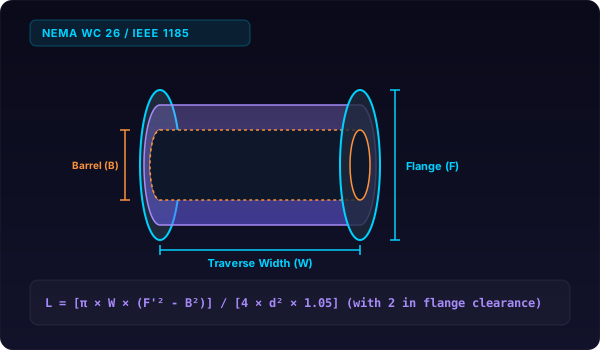
Reel capacity uses L = [π × W × (F’² - B²)] / [4 × d² × 1.05]. A drum with 48-inch flange, 24-inch core, 30-inch traverse, and 1-inch cable holds 1,570 feet with 2-inch flange clearance.
Electrical contractors, utility distribution engineers, and cable manufacturers must accurately determine how much wire, electrical cable, wire rope, or fiber optic duct will fit onto a shipping spool or payoff drum. Under-filling a reel wastes transportation space and increases shipping costs, while over-filling damages the outer cable jacket during transport.
The Formula: Winding Volume and NEMA WC 26 Derivation
A cable reel is a hollow cylinder of winding space bounded by the barrel core, the flange perimeter, and the traverse width. Standard calculations follow the National Electrical Manufacturers Association Wire and Cable Packaging Standard (NEMA WC 26 / EIC CS-15).
Effective Flange Diameter (F')
To guarantee the mandatory 2.0-inch (50 mm) safety clearance from the top edge of the flange:
F' = F - 2CWhere F is the nominal flange diameter and C is the radial clearance (typically C = 2.0 inches or 0.050 meters).
Hollow Cylinder Winding Volume
The total usable winding space is a hollow cylinder formed by subtracting the solid barrel cylinder from the outer effective cylinder:
V_winding = (π × (F'^2 - B^2) × W / 4)Where:
F'is the effective flange diameter.Bis the central drum/barrel diameter.Wis the internal traverse width between flanges.
For more on computing the wall volume of hollow cylinders, see our hollow cylinder calculator and our wire spool volume guide.
The NEMA Standard Length Formula
Each single turn of cable of outside diameter d occupies an effective cross-sectional footprint of approximately d^2 × k_pack, where k_pack is the packing factor (typically 1.05 to 1.15 to account for real-world winding imperfections):
L = \frac(V_winding)(A_cable footprint) = (π × W × (F'^2 - B^2) / 4 × d^2 × 1.05)When working in US Customary units with reel dimensions (F, B, W, d) in inches, dividing by 12 converts linear length to feet:
L_feet = \frac(π × W_in × (F_in'^2 - B_in^2))(4 × 12 × d_in^2 × 1.05) = \frac(π × W_in × (F_in'^2 - B_in^2))(50.4 × d_in^2)In SI Metric units with dimensions in millimeters, dividing by 1,000 converts length to meters:
L_meters = \frac(π × W_mm × (F_mm'^2 - B_mm^2))(4 × 1000 × d_mm^2 × 1.05) = \frac(π × W_mm × (F_mm'^2 - B_mm^2))(4200 × d_mm^2)Reference Data: Standard NEMA Wooden and Steel Reel Sizes
The following reference table lists standard NEMA WC 26 wooden and returnable steel reel sizes, tare weights, and estimated cable capacities (with 2-inch flange clearance and 1.05 packing factor).
| NEMA Reel Designation | Flange Dia F (in) | Barrel Dia B (in) | Traverse W (in) | Tare Weight (lbs) | Max Weight Rating (lbs) | Capacity: 0.50″ Cable | Capacity: 1.00″ Cable | Capacity: 1.50″ Cable |
|---|---|---|---|---|---|---|---|---|
| NEMA 24-15 | 24 in | 12 in | 15 in | 35 lbs | 1,000 lbs | 1,150 ft | 287 ft | 127 ft |
| NEMA 30-18 | 30 in | 14 in | 18 in | 60 lbs | 1,800 lbs | 2,630 ft | 657 ft | 292 ft |
| NEMA 36-22 | 36 in | 18 in | 22 in | 95 lbs | 3,000 lbs | 4,920 ft | 1,230 ft | 546 ft |
| NEMA 42-28 | 42 in | 20 in | 28 in | 145 lbs | 4,500 lbs | 9,560 ft | 2,390 ft | 1,062 ft |
| NEMA 48-32 | 48 in | 24 in | 32 in | 220 lbs | 6,500 lbs | 15,360 ft | 3,840 ft | 1,706 ft |
| NEMA 54-36 | 54 in | 28 in | 36 in | 310 lbs | 8,500 lbs | 23,280 ft | 5,820 ft | 2,586 ft |
| NEMA 60-40 | 60 in | 32 in | 40 in | 450 lbs | 12,000 lbs | 34,280 ft | 8,570 ft | 3,808 ft |
| NEMA 72-48 | 72 in | 36 in | 48 in | 750 lbs | 18,000 lbs | 57,800 ft | 14,450 ft | 6,422 ft |
| NEMA 84-54 | 84 in | 42 in | 54 in | 1,200 lbs | 25,000 lbs | 90,800 ft | 22,700 ft | 10,088 ft |
Worked Examples
Worked Example 1: Metric Wooden Drum for Low-Voltage Armored Power Cable
A European electrical contractor purchases a four-core armored low-voltage power cable with an overall outside diameter of 25.0 mm. The supplier packages the cable on a standard wooden drum with Flange F = 1200 mm, Barrel B = 600 mm, Traverse W = 800 mm, and an engineered clearance allowance of C = 50 mm. Calculate effective flange diameter, usable winding volume in cubic meters, and maximum cable length in meters.
Step 1: Calculate effective flange diameter.
F' = F - 2C = 1200 mm - 2(50 mm) = 1100 mmStep 2: Calculate usable winding volume.
V_winding = (π × (F'^2 - B^2) × W / 4) = (3.14159265 × (1100^2 - 600^2) × 800 / 4) = (3.14159265 × (1210000 - 360000) × 800 / 4) = (3.14159265 × 850000 × 800 / 4) = 534070751 mm^3 = 0.534071 m^3Step 3: Calculate cable winding length using metric NEMA formula.
L = (π × W × (F'^2 - B^2) / 4200 × d^2) = (3.14159265 × 800 × (1100^2 - 600^2) / 4200 × 25^2) = (3.14159265 × 800 × 850000 / 4200 × 625) = (2136283004 / 2625000) = 813.82 metersThe reel holds approximately 813.8 meters of armored power cable.
Worked Example 2: Imperial Control Cable Spool
An automation plant requires bulk multiconductor control wire with an outside diameter of 0.375 inches (3/8 in). The technician winds the cable onto a plywood spool with Flange F = 24.0 in, Barrel B = 12.0 in, Traverse W = 14.0 in, maintaining a 1.5-inch flange clearance (C = 1.5 in). Calculate effective flange diameter and total wire length in feet.
Step 1: Calculate effective flange diameter.
F' = 24.0 in - 2(1.5 in) = 21.0 inStep 2: Compute length in feet using imperial formula.
L_feet = (π × W × (F'^2 - B^2) / 50.4 × d^2) = (3.14159265 × 14.0 × (21.0^2 - 12.0^2) / 50.4 × (0.375)^2) = (3.14159265 × 14.0 × (441.0 - 144.0) / 50.4 × 0.140625) = (43.982297 × 297.0 / 7.0875) = (13062.74 / 7.0875) = 1843.07 feetThe spool comfortably accommodates 1,843 feet of control wire. You can verify imperial length and cylinder calculations with our cylinder volume in inches tool and cylinder volume in feet tool.
Worked Example 3: Edge Case Heavy Medium-Voltage Armored Cable and Payload Weight Limit
An electric utility is ordering 15kV three-conductor shielded armored medium-voltage cable with an outside diameter of 2.50 inches and a linear weight of 6.80 pounds per foot. The engineer selects a large steel reel with Flange F = 84.0 in, Barrel B = 48.0 in (exceeding the cable’s mandatory 24.0-inch minimum bend radius), Traverse W = 42.0 in, and Clearance C = 2.0 in (F' = 80.0 in). The empty steel reel weighs 850 lbs. Calculate total cable length capacity, cable weight, gross shipping weight, and verify against a 12,000-lb trailer payload rating.
Step 1: Calculate cable winding length capacity.
L = (π × 42.0 × (80.0^2 - 48.0^2) / 50.4 × (2.50)^2) = (3.14159265 × 42.0 × (6400.0 - 2304.0) / 50.4 × 6.25) = (131.94689 × 4096.0 / 315.0) = (540454.46 / 315.0) = 1715.73 feetStep 2: Calculate total cable mass.
Cable Weight = 1715.73 ft × 6.80 lb/ft = 11666.96 lbsStep 3: Calculate gross package weight.
Gross Weight = Cable Weight + Reel Tare Weight = 11666.96 + 850.0 = 12516.96 lbsStep 4: Verify payload limit. Gross weight (12,517 lbs) exceeds the 12,000-lb trailer limit. The engineer must restrict the order length to:
Max Allowable Cable Weight = 12000 - 850 = 11150 lbsMax Allowable Length = (11150 lbs / 6.80 lb/ft) = 1639.7 feetThe reel is short-wound to 1,600 feet to guarantee legal highway trailer transport. For related calculations on heavy coils and wound rolls, see our steel coil volume and weight calculation guide.
Common Mistakes in Cable Drum Sizing
-
Ignoring Mandatory 2-Inch Flange Clearance Calculating winding volume up to the absolute outer flange rim (
Finstead ofF - 2C) results in cable protruding past the flange edges. During transport, vibrations cause the outermost layer to rub against truck bed rails or adjacent drums, crushing insulation. Always subtract2Cbefore applying formulas. -
Selecting a Barrel Diameter Below Minimum Bending Radius Winding thick power cables or fiber optic bundles around small drum cores violates IEEE 1185 bending limits. Bending high-voltage cross-linked polyethylene (XLPE) cable tighter than its allowable radius induces severe mechanical strain in the copper tape shield and semiconducting screen, causing dielectric failure during subsequent high-pot testing.
-
Treating Cable Diameter as a Theoretical Circle Without Ovality Tolerances Cable extrusion is not perfectly circular. Multi-conductor twisted cables exhibit periodic outer diameter variations of +3% to +7% across laying seams. Furthermore, soft outer jackets flatten slightly under tension. Failing to apply a 1.05 to 1.15 packing factor results in the cable overflowing the drum several layers before target length is reached.
-
Neglecting Gross Reel Package Weight on Rigging and Crane Slings Calculating length without verifying total package weight leads to dangerous rigging overloads on job sites. A full wooden reel of heavy armored copper feeder cable can easily exceed 10,000 pounds, requiring specialized spreader bars and heavy-duty four-point rigging. Always calculate total weight using our cylinder weight calculator.
-
Disregarding Flange Flexing and Traverse Expansion Under Winding Tension High-tension winding machines compress inner layers, exerting tremendous outward axial thrust against wooden flange sides. In wide drums, flange deflection can increase traverse width at the outer perimeter while pinching cable near the arbor hole. Use heavy-duty bolted steel reels for high-tension utility transmission conductors.
Related Electrical and Coil Volume Resources
For related engineering calculations on hollow cylinders, spools, and wraps, explore our technical guides:
- How to find the volume of a wire spool
- Steel coil volume and weight calculation
- HVAC round duct volume and air changes per hour
- Hydraulic accumulator sizing and gas precharge volume
- How to calculate pipe insulation volume
- Hollow cylinder volume calculator
- Cylinder volume from diameter calculator
Accurate reel capacity calculations eliminate job site splice waste and ensure safe transportation and tension pay-off for electrical utility and telecommunication installations.