Engineering & Industrial · August 27, 2026
Hydraulic Accumulator Sizing and Gas Precharge Volume
Calculate hydraulic accumulator shell size, gas precharge pressure, and usable fluid discharge volume. Explains adiabatic and isothermal ISO 5598 formulas.

- Hydraulic Accumulator Sizing and Gas Precharge Volume
- The Formula: Polytropic Gas Law and Usable Fluid Discharge
- Usable Discharged Fluid Volume (Δ V)
- Required Accumulator Shell Volume (V_0)
- Optimal Precharge Pressure Selection Rules
- Reference Data: Standard Hydraulic Accumulator Sizes and Pressure Ratings
- Worked Examples
- Worked Example 1: Metric Emergency Brake Actuator (Fast Adiabatic Discharge)
- Worked Example 2: Imperial Hydraulic Stamping Press Auxiliary Circuit (Slow Isothermal Discharge)
- Worked Example 3: Edge Case Sub-Zero Cold Weather Precharge Pressure Drop
- Common Mistakes in Accumulator Sizing and Maintenance
- Mounting Orientation and Flow Velocity Limits
- Routine Precharge Inspection Schedule and Safety Protocols
- Related Fluid Power and Pressure Vessel Resources
Hydraulic Accumulator Sizing and Gas Precharge Volume
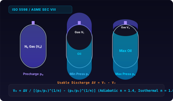
Accumulator sizing uses V0 = ΔV / [(p0/p1)^(1/n) - (p0/p2)^(1/n)]. To deliver 2.5 gallons between 3,000 PSI and 2,000 PSI with 1,800 PSI precharge, a 10.8 gallon nitrogen bottle is required.
Hydraulic accumulators store potential energy in the form of compressed nitrogen gas separated from hydraulic fluid by an elastomeric bladder, piston, or diaphragm. Whether providing emergency power for fail-safe brake actuators or absorbing pressure spikes, proper volumetric sizing under ISO 5598 standards prevents premature bladder fatigue and pump cavitation.
The Formula: Polytropic Gas Law and Usable Fluid Discharge
Gas compression and expansion inside a cylindrical accumulator shell follow the polytropic gas relationship:
p_0 × V_0^n = p_1 × V_1^n = p_2 × V_2^nWhere:
p_0is the dry nitrogen gas precharge pressure (absolute pressure,psiaorbar absolute).V_0is the total internal accumulator shell volume.p_1is the minimum operating system pressure.V_1is the gas volume at minimum working pressure.p_2is the maximum system working pressure.V_2is the gas volume at maximum working pressure.nis the polytropic exponent:n = 1.0for isothermal conditions (slow charging/discharging> 3 minutes).n = 1.4for adiabatic conditions (fast discharge< 60 seconds).n = 1.1 to 1.3for intermediate machine cycles.
Usable Discharged Fluid Volume (Δ V)
The fluid volume Δ V pushed out of the accumulator between maximum pressure p_2 and minimum pressure p_1 equals the expansion of the nitrogen gas volume:
Δ V = V_1 - V_2 = V_0 ≤ft[≤ft((p_0 / p_1)\right)^1/n - ≤ft((p_0 / p_2)\right)^1/n\right]Required Accumulator Shell Volume (V_0)
Rearranging to solve for the required total accumulator capacity:
V_0 = (Δ V / ≤ft(\frac(p_0){p_1)\right)^1/n - ≤ft((p_0 / p_2)\right)^1/n}For calculations involving hydraulic actuators, pistons, and fluid reservoirs, explore our hydraulic cylinder calculator and our hydraulic cylinder rod volume guide.
Optimal Precharge Pressure Selection Rules
Under standard fluid power engineering practice:
- Energy Storage / Emergency Power:
p_0 = 0.90 × p_1 - Pulsation Dampening (Piston Pumps):
p_0 = 0.60 to 0.75 × p_mean - Hydraulic Line Shock Absorber:
p_0 = 0.80 to 0.90 × p_static
Reference Data: Standard Hydraulic Accumulator Sizes and Pressure Ratings
The following engineering reference table summarizes commercial bladder, piston, and diaphragm accumulator specifications under ASME Section VIII Division 1 and ISO 16528 standards.
| Nominal Size (Gallons / Liters) | Shell Type | Max Working Pressure (PSI / Bar) | Usable ΔV at 3,000 to 2,000 PSI (Adiabatic n=1.4) | Usable ΔV at 3,000 to 2,000 PSI (Isothermal n=1.0) | Standard Nitrogen Precharge Port | Shell Weight (lbs / kg) |
|---|---|---|---|---|---|---|
| 1.0 Liter (0.26 gal) | Diaphragm | 3,000 PSI (210 bar) | 0.23 Liters (0.06 gal) | 0.30 Liters (0.08 gal) | 1/4″ NPT / 5/8″-18 UNF | 8.8 lbs (4.0 kg) |
| 2.5 Gallons (9.5 Liters) | Bladder | 3,000 PSI (210 bar) | 0.58 Gallons (2.20 L) | 0.75 Gallons (2.85 L) | 7/8″-14 UNF / ISO 228 | 65 lbs (29.5 kg) |
| 5.0 Gallons (18.9 Liters) | Bladder | 3,000 PSI (210 bar) | 1.16 Gallons (4.39 L) | 1.50 Gallons (5.68 L) | 7/8″-14 UNF / ISO 228 | 115 lbs (52.2 kg) |
| 10.0 Gallons (37.9 Liters) | Bladder | 3,000 PSI (210 bar) | 2.32 Gallons (8.78 L) | 3.00 Gallons (11.36 L) | 7/8″-14 UNF / ISO 228 | 210 lbs (95.3 kg) |
| 15.0 Gallons (56.8 Liters) | Bladder | 3,000 PSI (210 bar) | 3.48 Gallons (13.17 L) | 4.50 Gallons (17.03 L) | 7/8″-14 UNF / ISO 228 | 310 lbs (140.6 kg) |
| 20.0 Gallons (75.7 Liters) | Piston | 5,000 PSI (350 bar) | 4.64 Gallons (17.56 L) | 6.00 Gallons (22.71 L) | 7/8″-14 UNF / ISO 228 | 520 lbs (235.9 kg) |
| 30.0 Gallons (113.6 Liters) | Piston | 5,000 PSI (350 bar) | 6.96 Gallons (26.35 L) | 9.00 Gallons (34.07 L) | 7/8″-14 UNF / ISO 228 | 780 lbs (353.8 kg) |
| 50.0 Gallons (189.3 Liters) | Piston | 5,000 PSI (350 bar) | 11.60 Gallons (43.91 L) | 15.00 Gallons (56.78 L) | 7/8″-14 UNF / ISO 228 | 1,250 lbs (567 kg) |
Worked Examples
Worked Example 1: Metric Emergency Brake Actuator (Fast Adiabatic Discharge)
An industrial crane requires an emergency fail-safe braking system. In the event of electric power loss, the accumulator must supply 4.0 liters of hydraulic fluid (Δ V = 4.0 L) within 0.5 seconds to engage the spring-loaded calipers. Operating conditions: maximum system pressure p_2 = 210.0 bar, minimum working pressure to hold brakes p_1 = 140.0 bar. Fast discharge requires the adiabatic exponent n = 1.4. Calculate the nitrogen precharge pressure, the required shell volume V_0, and select a standard commercial size.
Step 1: Set nitrogen precharge pressure (p_0).
p_0 = 0.90 × p_1 = 0.90 × 140.0 bar = 126.0 barStep 2: Calculate pressure ratios raised to (1 / 1.4 = 0.714286).
(p_0 / p_1) = (126.0 / 140.0) = 0.900000 → (0.900000)^0.714286 = 0.927655(p_0 / p_2) = (126.0 / 210.0) = 0.600000 → (0.600000)^0.714286 = 0.694270Step 3: Calculate difference in expansion factors.
Denominator = 0.927655 - 0.694270 = 0.233385Step 4: Compute total accumulator shell volume (V_0).
V_0 = (Δ V / Denominator) = (4.0 liters / 0.233385) = 17.1391 litersStep 5: Select commercial accumulator. A standard 20.0-liter bladder accumulator is selected. You can check internal volume conversions with our cylinder volume in liters tool.
Worked Example 2: Imperial Hydraulic Stamping Press Auxiliary Circuit (Slow Isothermal Discharge)
A 500-ton hydraulic stamping press requires an auxiliary volume of 5.0 gallons (Δ V = 5.0 gallons) over a 30-second dwell cycle where heat dissipates through the piping (isothermal n = 1.0). The pump operates at a relief setting of p_2 = 3,000 PSI, and the minimum clamping pressure is p_1 = 2,200 PSI. Nitrogen precharge is set to p_0 = 0.90 × 2,200 = 1,980 PSI. Calculate the required accumulator shell volume in gallons and cubic inches.
Step 1: Calculate isothermal expansion factors (n = 1.0).
(p_0 / p_1) = (1980 PSI / 2200 PSI) = 0.900000(p_0 / p_2) = (1980 PSI / 3000 PSI) = 0.660000Step 2: Calculate denominator difference.
Denominator = 0.900000 - 0.660000 = 0.240000Step 3: Calculate required shell volume (V_0).
V_0 = (5.0 gallons / 0.240000) = 20.8333 gallonsStep 4: Convert to cubic inches.
V_0 = 20.8333 gal × 231 cu in/gal = 4812.50 cubic inchesThe engineer specifies a standard 25.0-gallon piston accumulator. You can verify cubic inch dimensions with our cylinder volume in cubic inches tool.
Worked Example 3: Edge Case Sub-Zero Cold Weather Precharge Pressure Drop
A mobile hydraulic drilling rig operates in sub-zero oilfield conditions at -20.0^\circF (-28.9^\circC). The technician charged the 10.0-gallon bladder accumulator to p_0 = 1,500.0 PSI in a heated service bay at 70.0^\circF (21.1^\circC). Calculate the actual cold precharge pressure in the field using Gay-Lussac’s Law and the resulting loss in usable discharge fluid volume between 3,000 PSI and 2,000 PSI.
Step 1: Convert temperatures to absolute Rankine scale.
T_shop = 70.0^\circF + 459.67 = 529.67 RT_field = -20.0^\circF + 459.67 = 439.67 RStep 2: Calculate cold precharge pressure (p_0,cold).
p_0,cold = p_0,shop × \frac(T_field)(T_shop) = 1500.0 PSI × (439.67 / 529.67) = 1500.0 × 0.830083 = 1245.12 PSIStep 3: Compare usable discharge volume (Δ V) at adiabatic n = 1.4.
- At Shop Precharge (1,500 PSI):
Δ V_shop = 10.0 × ≤ft[≤ft((1500 / 2000)\right)^0.714286 - ≤ft((1500 / 3000)\right)^0.714286\right] = 10.0 × [0.814240 - 0.609536] = 2.0470 gallons- At Cold Field Precharge (1,245.12 PSI):
Δ V_cold = 10.0 × ≤ft[≤ft((1245.12 / 2000)\right)^0.714286 - ≤ft((1245.12 / 3000)\right)^0.714286\right] = 10.0 × [0.712104 - 0.533036] = 1.7907 gallonsStep 4: Calculate loss in usable hydraulic power.
Reduction = (2.0470 - 1.7907 / 2.0470) × 100 = 12.52\%The cold temperature reduces available fluid volume by 12.5%. The technician must precharge to 1,807 PSI in the shop to achieve the design 1,500 PSI at -20^\circF. For more on temperature effects on industrial fluid systems, see our guide on transformer cylindrical tank oil capacity.
Common Mistakes in Accumulator Sizing and Maintenance
-
Precharging with Compressed Air Instead of Pure Dry Nitrogen Using shop air or oxygen is the most dangerous error in fluid power. Compressing air and hydraulic oil vapor under high pressure generates intense heat of compression, causing auto-ignition and vessel explosion. Only use 99.9% pure dry industrial nitrogen (N2) with a certified charging manifold.
-
Setting Precharge Pressure Equal to or Greater than Working Pressure Setting
p_0 ≥ p_1causes the rubber bladder to expand completely against the metal shell and fluid port poppet at the end of every discharge cycle. The continuous mechanical impact extrudes and pinches the elastomeric bladder, causing tearing within hundreds of cycles. Maintainp_0 ≤ 0.90 × p_1. -
Using Isothermal Formulas for Fast Emergency Cycles Applying
n = 1.0rather thann = 1.4for emergency discharge cycles taking under 10 seconds under-sizes the required accumulator shell by 25% to 35%. Because nitrogen cools rapidly during fast expansion, gas pressure drops faster than isothermal formulas predict, leaving the actuator starved of fluid. -
Ignoring Gauge Pressure versus Absolute Pressure in Gas Formulas The polytropic gas law requires absolute pressures (
psiaorbar absolute). For high-pressure systems (> 2,000 PSI), atmospheric pressure (14.7 PSI) has a minor effect, but in low-pressure accumulators operating below300 PSI, failing to add atmospheric pressure introduces a 5% to 10% mathematical error. -
Checking Precharge Pressure While Hydraulic Fluid Is Under Pressure Connecting a charging kit to an accumulator while the hydraulic pump is running or the circuit holds residual pressure measures current system hydraulic pressure, not the nitrogen precharge. The hydraulic system must be fully depressurized and vented to the reservoir before attaching the gas chuck.
Mounting Orientation and Flow Velocity Limits
Accumulator installation geometry affects internal fluid mechanics and bladder service life. Bladder accumulators should always be mounted vertically with the gas valve on top and the fluid port pointing straight down. Mounting a bladder accumulator horizontally causes the rubber bladder to rub continuously against the steel shell during charge and discharge cycles, wearing through the elastomer wall.
For horizontal mounting applications, piston accumulators are preferred. Piston accumulators feature machined internal cylinder bores and PTFE wear rings that support the piston mass without excessive radial deflection.
Flow velocities at the accumulator fluid port must be kept below twenty-five feet per second (7.5 meters per second). Excessive discharge velocity can draw the bladder into the fluid port poppet valve before the poppet closes, tearing the bottom of the bladder. If circuit discharge flow exceeds poppet ratings, designers install high-flow accumulator manifolds with dual fluid ports or multiple parallel accumulator bottles.
Routine Precharge Inspection Schedule and Safety Protocols
Nitrogen gas slowly permeates through elastomeric bladders over time. Bladder accumulators typically lose one to three percent of their precharge pressure per year through micro-permeation. Fluid power maintenance standards recommend checking nitrogen precharge pressure thirty days after initial commissioning, and every six months thereafter.
When servicing accumulators, always follow lockout and tagout safety procedures. Never weld, drill, or machine any part of an accumulator shell. Any mechanical alteration weakens the forged steel pressure vessel, leading to catastrophic failure under hydraulic pressure.
Related Fluid Power and Pressure Vessel Resources
For related engineering formulas, cylinder calculators, and fluid mechanics guides, explore our resources:
- Volume of a hydraulic cylinder rod
- Hydraulic cylinder volume calculator
- Cylindrical pressure vessel volume and wall thickness
- Propane tank fill percentage and the 80 percent safe fill rule
- Cable drum and reel capacity, how much cable fits
- Transformer cylindrical tank oil capacity
- Steel coil volume and weight calculation
- Engine cylinder displacement calculator
Correct accumulator sizing and temperature-compensated precharging guarantee reliable hydraulic energy storage and protect components from high-frequency pressure spikes.